

- Stock: In Stock
- Model: ROVER 5
- Weight: 725.00g
- Dimensions: 24.50cm x 22.50cm x 7.50cm
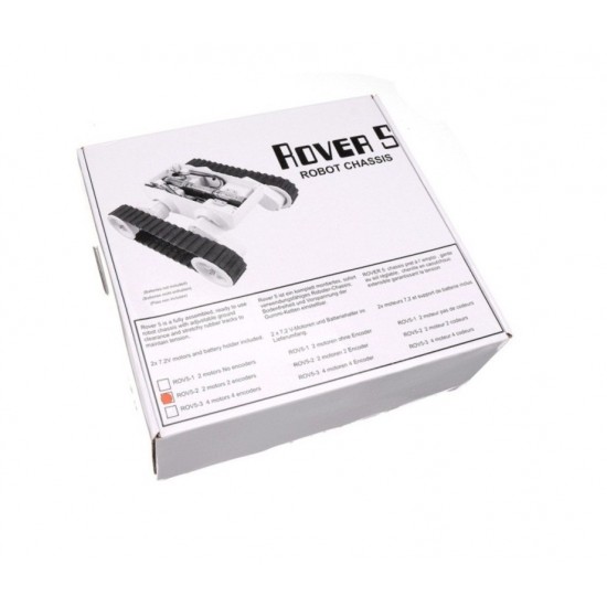
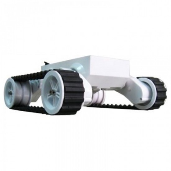
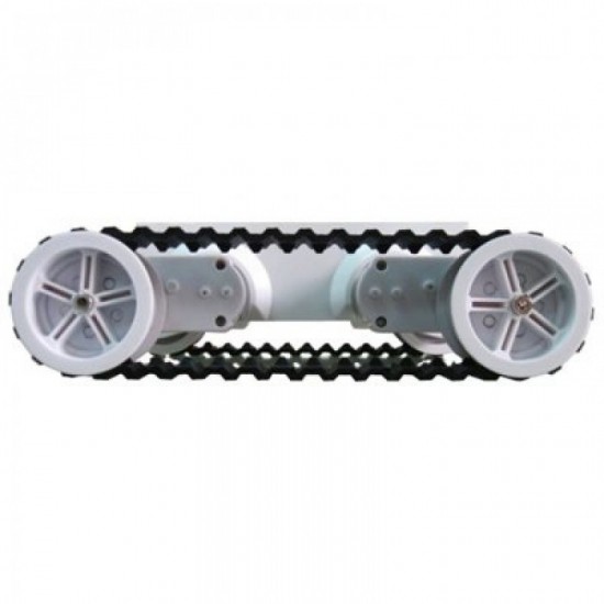
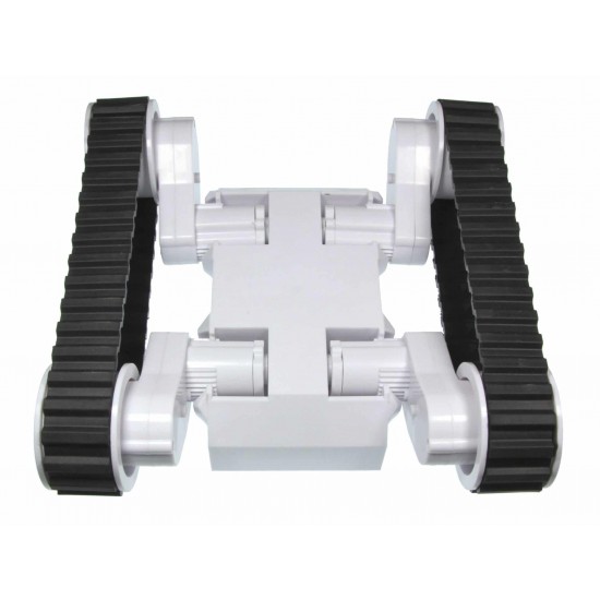
Rover 5 Robot Platform (2 motors + 2 encoders)
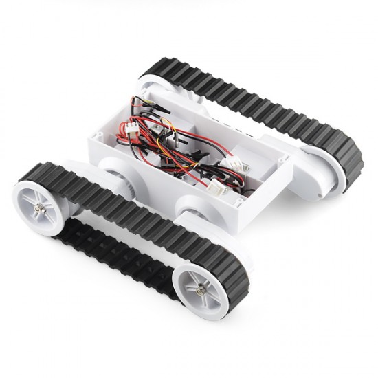
If you're looking for a base for your next robot, look no further than the Rover 5. The Rover 5 uses 2 independent motors, each with an optical quadrature encoder and gearbox. The entire gearbox assembly can be rotated at 5 degree increments for different clearance configurations. You can even replace the tank treads with traditional wheels.
This isn't a wimpy or flimsy robot base. Weighing in at over 2.5 pounds without batteries, this base is heavy duty and can drive over quite a bit. Check the manual below for dimensional drawings.
Each gearbox has an 87:1 ratio includes a hall effect quadrature enco d er that gives 1000 pulses over 3 revolutions of the output shaft. The chassis can be upgraded to include two motors and encoders making it ideal for mecanum wheels.
Inside of the chassis are 2 noise suppression coils at the bottom and a battery holder that accepts 6x AA batteries. It is recommended to use NiMh batteries as they last longer and have a higher current output than Alkaline batteries.
How to use a quadrature encoder
A quadrature encoder, also known as an incremental rotary encoder measures the speed and direction of a rotating shaft. Quadrature encoders can use different types of sensors, optical and hall effect are both commonly used. There are two hall effect sensors on the PCB that respond to an 8-pole disc magnet mounted on one of the gears . No matter what type of sensors are used the output is typically two square waveforms 90° out of phase.
If you only wish to monitor the speed of rotation then you can use either output and simply measure the frequency. The reason for having two outputs is that you can also determine the direction of shaft rotation by looking at the pattern of binary numbers generated by the two outputs.
By feeding both outputs into an XOR gate (exclusive OR) you will get a square wave with twice the frequency regardless of direction. This can be useful as it allows one interrupt pin to monitor both encoder inputs.
Features:
- Adjustable gear box angles
- 2 independent DC motors
- 2 independent optical encoders
- Thick rubber tank treads
- 6x AA battery holder
- 10Kg/cm stall torque per motor
Documents:


